
Polymer concrete drainage channels
A drainage channel is part of a complete surface-water system. Its dimensions must be coordinated with the grating, finished levels, outlet and surrounding construction.
Available channel dimensions
The drawing defines A as channel width, B as unit length, C as overall channel height and D as metal-strip height. All dimensions are in millimetres.
The table groups channels by width. Each C range shows the minimum and maximum channel height for that width; it does not indicate that every intermediate height is available. The metal-strip height D is selected with the grating arrangement. Confirm the exact C/D configuration in the quotation.
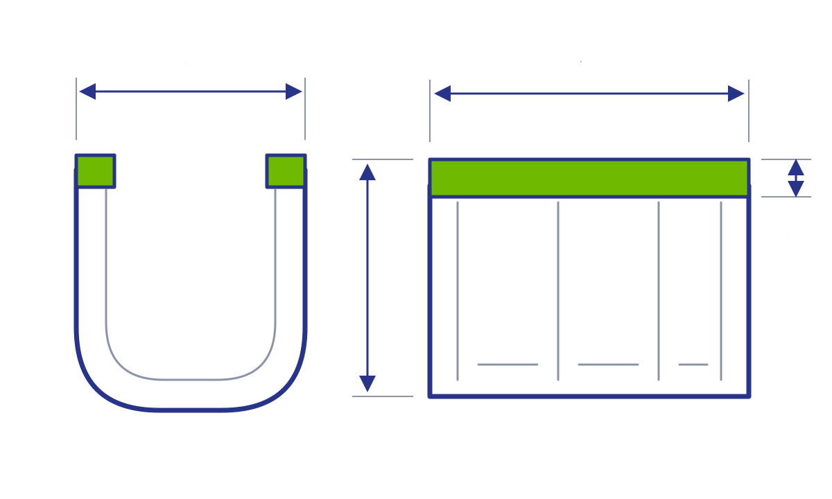
| A — width (mm) | B — length (mm) | C — height range (mm) |
|---|---|---|
| 125 | 1000 | 60–200 |
| 150 | 1000 | 150 |
| 200 | 1000 | 60–400 |
| 250 | 1000 | 70–300 |
| 300 | 1000 | 70–380 |
| 400 | 1000 | 180–400 |
Coordinate drainage and structural requirements
Describe the catchment, flow direction, discharge point and available installation depth. Channel width alone does not establish hydraulic capacity. The outlet arrangement and surrounding levels can restrict drainage even where the channel itself is large enough.
State the traffic location and proposed grating. Any load requirement must be evaluated for the channel, cover, edge detail and installation together. Manhole-cover classifications should not be transferred automatically to a channel system.
Information for a channel enquiry
Provide the overall run length, corner or junction requirements, outlet positions, finished levels and quantities. Identify the channel code if known and describe any unusual chemical or temperature exposure. Request a coordinated proposal for the channel and grating rather than ordering them independently from nominal widths.
Installation bedding, concrete surround, joints and interfaces should follow the project detail and the selected system instructions. Confirm these before finalising excavation or adjacent surfacing.