GRP grating fixings
Grating fixings secure a panel to its supporting structure and help control movement. The fixing must suit the grating and the support; a clip description alone is not an installation design.
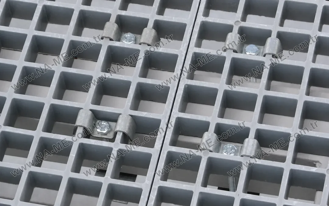
M-type assembly: the clip holds the panel down onto the supporting flange.
M-type assembly examples from the NA-ME product record
The first three assemblies below are grouped under h25–h30–h38 in the NA-ME product record, and the second three under h50. These are the panel-height groups used in that record; confirm compatibility with your selected panel and support. Mass is the listed mass per assembly.
| Code | Panel height group | Material | Mass (kg/set) |
|---|---|---|---|
| CM-M-101 | h25–h30–h38 | Galvanised | 0.127 |
| CM-M-201 | h25–h30–h38 | AISI 304 | 0.105 |
| CM-M-301 | h25–h30–h38 | AISI 316 | 0.105 |
| CM-M-102 | h50 | Galvanised | 0.127 |
| CM-M-202 | h50 | AISI 304 | 0.105 |
| CM-M-302 | h50 | AISI 316 | 0.105 |
Check the entire connection
Give the grating code, mesh and height, support flange size and thickness, access from below and any limits on drilling. State whether panels must be lifted periodically. A panel-to-panel connector and a hold-down assembly serve different functions; do not treat one as a substitute for the other.
Choose the metal finish or grade for the chemical and atmospheric exposure. A corrosion-resistant grating does not make every metallic fixing suitable for the same environment. Confirm compatibility of the bolt, washer, lower component and upper clip as one assembly.
Installation information to request
The fixing layout, fastener selection, tightening method and any required inspection procedure should be provided for the actual support arrangement. No universal clip spacing or tightening torque is specified here. Excessive tightening can damage a composite contact surface while inadequate restraint may permit movement.
Send a section through the panel and support, together with the panel schedule, for a coordinated fixing enquiry. Include cut panels, corners, access hatches and locations with uplift or vibration.